
This article has been machine-translated from Chinese. The translation may contain inaccuracies or awkward phrasing. If in doubt, please refer to the original Chinese version.
Chapter 4: Instruction Systems
4.1 Development and Performance Requirements of Instruction Systems
Basic Concepts of Instruction Systems
- Instruction: A command for the computer to perform a certain operation. From the perspective of computer architecture hierarchy, computer instructions can be divided into microinstructions, machine instructions, and macro instructions.
- Microinstructions are microprogramming-level commands that belong to hardware;
- Macro instructions are software instructions composed of multiple machine instructions, belonging to software;
- Machine instructions are between microinstructions and macro instructions, commonly referred to simply as instructions.
- Each instruction can perform an independent arithmetic or logical operation. The instructions discussed in this chapter are machine instructions.
- The collection of all machine instructions in a computer is called that computer's instruction set.
- The instruction set is an important factor characterizing a computer's performance. Its format and functions not only directly affect the machine's hardware structure but also directly affect system software and the machine's range of applications.
4.1.1 Development of Instruction Systems
Development History
-
In the 1950s, instruction sets had only a few dozen instructions including fixed-point addition/subtraction, logical operations, data transfer, branching, etc.
-
In the late 1960s, multiplication/division, floating-point, decimal, string processing, and other instructions were added, with instruction counts reaching one to two hundred. Addressing modes also became more diverse, and computer series began to appear.
-
In the late 1970s, most computer instruction sets grew to several hundred instructions. These computers are called Complex Instruction Set Computers (CISC).
- However, such large instruction sets not only extended development cycles and made it difficult to ensure correctness and maintainability, but also wasted hardware resources due to the extensive use of rarely-used complex instructions. This gave rise to the so-called 80/20 rule of instruction sets.
- That is, the most frequently used simple instructions account for only 20% of total instructions, but appear in 80% of program execution.
-
Thus, Reduced Instruction Set Computers (RISC) were proposed, suitable for VLSI technology implementation.
4.1.2 Performance Requirements for Instruction Systems
- Completeness: Completeness means the instruction set directly provides sufficient instructions for writing various programs in assembly language, without needing software-based implementations. Completeness requires a rich, full-featured, and convenient instruction set. The most basic and essential instructions in a computer are relatively few. Many instructions can be implemented by programming with basic instructions.
- Effectiveness: Effectiveness means programs written using the instruction set can run with high efficiency. High efficiency mainly means programs occupy less memory and execute quickly.
- Regularity: Regularity includes symmetry, uniformity, and consistency of instruction and data formats.
- Symmetry: All registers and memory units in the instruction set can be treated equally, and all instructions can use various addressing modes.
- Uniformity: A type of operation instruction can support various data types, such as arithmetic instructions supporting byte, word, and double-word integer operations, decimal operations, and single/double-precision floating-point operations.
- Instruction and data format consistency: Instruction length and data length have a certain relationship for convenient processing and access. For example, instruction length and data length are usually integer multiples of byte length.
- Compatibility: Series computers share the same basic structure and common basic instruction set, so instruction sets are compatible, meaning basic software can be used across models. However, since different models are released at different times with differences in structure and performance, complete compatibility of all software is impossible. Only "upward compatibility" is achievable, meaning software running on lower-end machines can run on higher-end machines.
4.2 Instruction Format
- Instruction format: The structural form of an instruction word represented in binary code
- An instruction should reflect the following information:
- What operation to perform
- Where to get operands if needed
- Where to send results, where to get the next instruction
- Instruction format includes two aspects:
| Operation Code Field OP | Address Code Field A |
|---|---|
| Indicates the operation characteristics and function of the instruction | Specifies the addresses of operands involved in the operation |
4.2.1 Operation Code
- When designing a computer, an operation code must be specified for each instruction in the instruction set.
- The instruction's operation code OP indicates what type of operation the instruction should perform, such as addition, subtraction, multiplication, division, load, store, etc. Different instructions are represented by different encodings of the operation code field, with each encoding representing one instruction. For example, operation code 001 can specify addition; operation code 010 can specify subtraction.
- The number of bits in the operation code field generally depends on the scale of the computer's instruction set. Larger instruction sets require more bits to represent each specific instruction. For example, an instruction set with 32 instructions requires a 5-bit operation code. Generally, an n-bit operation code can represent up to 2n instructions.
4.2.2 Address Code (Key Topic)
- An instruction can be called a zero-address, one-address, two-address, or three-address instruction based on how many operand addresses it contains.
Zero-Address Instruction
| Operation Code OP |
|---|
Function: Instructions that don't require operands, such as "halt", "no operation", "clear", and other control instructions.
One-Address Instruction
| Operation Code OP | Operand A1 |
|---|
Functional description: OP (A1) -> A1 (AC) OP (A1) -> AC The operand is implicitly assumed to be in the accumulator AC
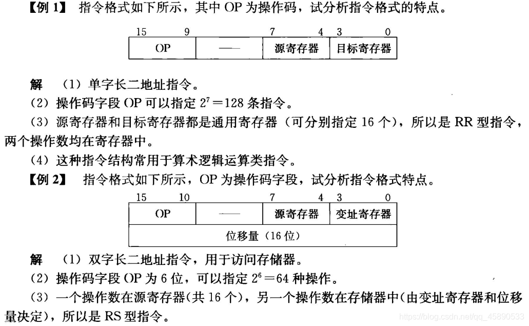
Two-Address Instruction
| Operation Code OP | Operand A1 | Operand A2 |
|---|
A1: Source/destination operand address A2: Destination/source operand address Functional description: (A1) OP (A2) -> A1 (A1) OP (A2) -> A2
Two-address instructions are classified by the physical location of operands:
- SS: Storage-to-Storage type
- RS: Register-to-Storage type
- RR: Register-to-Register type
Three-Address Instruction
| Operation Code | A1 | A2 | A3 |
|---|
A1: Operand address, also called source operand address A2: Operand address, also called destination operand address A3: Address for storing the result Functional description: (A1) OP (A2) -> A3
4.2.3 Instruction Word Length (Key Topic)
Concepts
- Instruction word length: The number of binary code bits contained in one instruction word
- Machine word length: The number of binary data bits a computer can directly process.
- Single-word instruction: An instruction whose word length equals the machine word length.
- Half-word instruction: An instruction whose word length equals half the machine word length.
- Double-word instruction: An instruction whose word length equals twice the machine word length.
Advantages and Disadvantages of Multi-Word Instructions
- Advantage: Provides sufficient address bits to solve the addressing problem of accessing any memory unit.
- Disadvantage: Requires two or more memory accesses to fetch a complete instruction, reducing CPU computation speed and occupying more storage space.
- Advantage of using equal-length instructions in an instruction set: All instruction word lengths are equal, simplifying instruction word structure and keeping instruction word length constant.
- Advantage of using variable-length instructions: Instruction word lengths vary according to instruction function, offering a flexible structure that efficiently utilizes instruction length, but instruction control is more complex.
- Problems typically assume a machine word length of 16 bits, as in the following problem:
4.3 Operand Types
4.3.1 General Data Types
- Address data: Addresses are actually a form of data.
- Numeric data: Three types of numeric data commonly used in computers:
- Fixed-point integers or fixed-point decimals, floating-point numbers, packed decimal numbers
- Character data: Text data or character strings; ASCII is widely used today.
- Logical data: A unit contains several binary bit items, each with a value of 1 or 0. When data is viewed this way, it is called logical data.
4.4 Instruction and Data Addressing Modes (Key Topic!)
- In memory, the methods for writing or reading operands or instruction words include address-specified mode, associative storage mode, and stack access mode. Almost all computers use address-specified mode for internal memory.
- Addressing mode: The method of forming an operand or instruction address
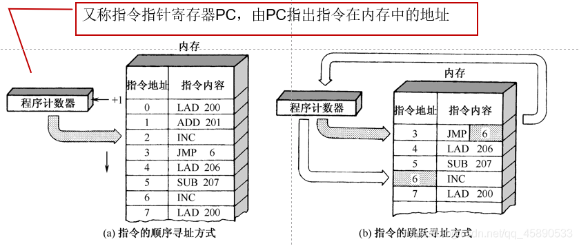
- Instruction addressing mode: Used to form the address of an instruction in memory
- Data addressing mode: Used to form the address of an operand in memory
4.4.1 Instruction Addressing Modes
- Sequential addressing mode
- Jump mode
4.4.2 Operand Addressing Modes
The method of finding the actual operand based on the address code field given in the instruction, i.e., the method of forming the effective address of the operand, is called the operand addressing mode. For example, a single-address instruction structure:
| Operation Code OP | Index X Indirect I | Formal Address A |
|---|---|---|
| Addressing mode characteristic bits | Offset |
The addressing process is the process of transforming the formal address of the operand into the effective address of the operand.
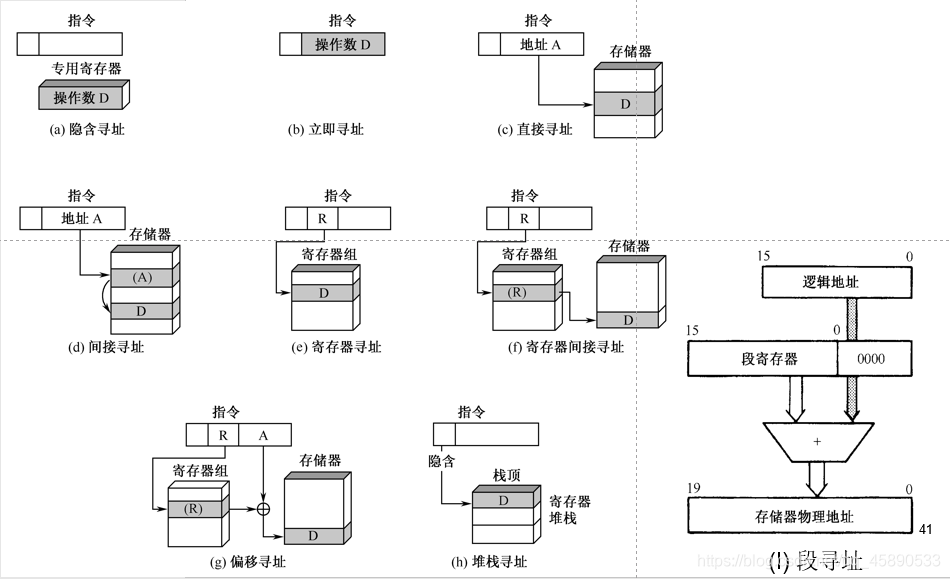
1. Implied Addressing
- Feature: The address of the operand is not explicitly given in the instruction, but is implicit
- In a single-address instruction format, the address field does not specify the second operand's address, but specifies the accumulator AC as the second operand address. AC is an implicit address.
2. Immediate Addressing
- Feature: Immediate addressing is a special addressing mode where the instruction's address field specifies not the operand address, but the operand itself
- The data is contained in the instruction; fetching the instruction also fetches the immediately usable operand, hence such operands are called immediate values.
- The operand included in the instruction is immediately available, saving memory access time.
- Instruction format: Operation Code OP Operand A
- Example: Instruction mov ax, 100
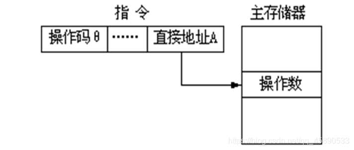
3. Direct Addressing
- Feature: The address code A given in the instruction is the effective address EA (Effective Address) of the operand, also called the direct address, i.e., EA = A.
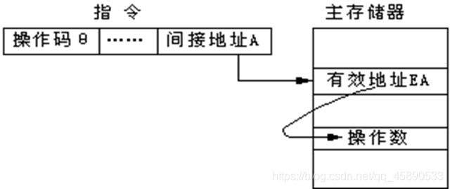
4. Indirect Addressing
- Feature: The formal address A in the instruction's address field is not the actual address of the operand, but rather a pointer to the operand's address, i.e., the content of A is the effective address of the operand: EA = (A) (essentially nesting)
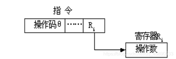
5. Register Addressing
- Feature: The operand is not in memory but stored in general-purpose registers
- The operand address given in the instruction is not a memory address, but a general-purpose register number. The instruction's operand is stored in the corresponding register, i.e., EA=Ri
Advantages
- Since registers are inside the CPU, fetching operands from registers is much faster than accessing main memory;
- Since the number of registers is small, the register number requires fewer bits, effectively reducing the length of the instruction's address code field.
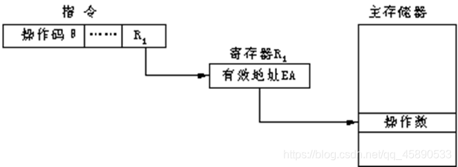
6. Register Indirect Addressing
-
Feature: The register content in the instruction is not the operand but the operand's address; the actual operand is in memory. The operand is stored in main memory, the operand's address is stored in a general-purpose register, and the instruction's address code part gives the register number, where EA=(Ri) (nested indirection)
-
Advantage: This addressing mode produces shorter instructions and requires only one memory access after instruction fetch to obtain the operand, making instruction execution faster than the indirect addressing mode described above. It is one of the most widely used addressing modes in computers.
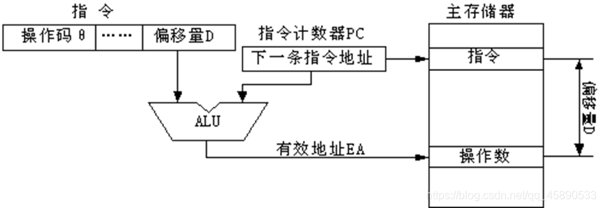
7. Displacement Addressing
- A combination of direct addressing and register indirect addressing
- Effective address: EA = A + (R), where A is the formal address
- Requires two address fields in the instruction, at least one of which is explicit.
- The formal address A is used directly.
- Three commonly used displacement addressing modes:
- Relative addressing, base addressing, indexed addressing
- Relative addressing: The program counter PC provides the base address, and the instruction's address code part provides a relative displacement D. The two are added to form the operand's effective address: EA = (PC) + D. The content of the program counter is the address of the current instruction.
- Base addressing: The base register can be set with a large number of bits, allowing addressing in a larger storage space.
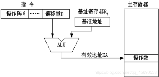
- Indexed addressing: Indexed addressing adds the base address A given in the instruction's address code part to the content of a specific index register Rx in the CPU to form the operand's effective address.

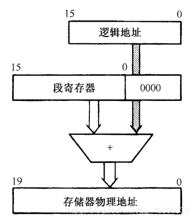
8. Segment Addressing Mode
- Microcomputers use segment addressing, which is essentially base addressing.
- The 1MB main memory space is divided into segments of maximum 64KB length. When addressing a specific memory unit, a base address register (segment register) plus a 16-bit offset provided by the instruction forms the actual 20-bit physical address.
9. Stack Addressing
- A temporary storage unit capable of storing and retrieving data
- Two forms: Register stack and memory stack
- Storage principle: Last In, First Out
- Data storage and retrieval are done through the top of the stack, requiring an implicit or explicit stack pointer
- Stack instructions: PUSH, POP
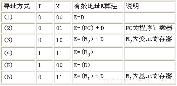
[Example 4] A two-address RS-type instruction has the following structure: 6 bits 4 bits 1 bit 2 bits 16 bits OP General Register I X Displacement D Where I is the indirect addressing flag bit, X is the addressing mode field, and D is the displacement field. Through combinations of I, X, and D, the following addressing modes can be formed:
喜欢的话,留下你的评论吧~