
This article has been machine-translated from Chinese. The translation may contain inaccuracies or awkward phrasing. If in doubt, please refer to the original Chinese version.
Chapter 6: Bus Systems
6.1 Bus Concepts and Structural Forms
6.1.1 Basic Bus Concepts (Key Topic)
A digital computer consists of several system functional components, which must work together to form a complete computer system.
Bus Definition
-
The various functional components of a computer cannot all be fully interconnected, so common information channels, i.e., buses, are needed.
-
A bus is the interconnection mechanism of a computer system, serving as a common pathway for data transfer between multiple system functional components. Through bus connections, computers exchange address, data, and control information between system functional components and operate on the basis of shared resources. Buses can be classified as follows:
-
Internal Bus: A bus connecting registers and arithmetic unit components within the CPU.
-
System Bus: An external bus connecting the CPU with other high-speed functional components of the computer system.
-
I/O Bus: A bus connecting medium and low-speed I/O devices.
Bus Characteristics
Bus characteristics can be classified into: physical characteristics, functional characteristics, electrical characteristics, and timing characteristics.
- Physical characteristics: The physical connection method of the bus (number of lines, plug and socket shapes, pin arrangements)
- Functional characteristics: The function of each line
- Electrical characteristics: The signal transmission direction and valid voltage range on each line.
- Timing characteristics: Specifies when each bus line is valid.
Bus Standardization
- Components with the same instruction set and functionality from different manufacturers can be used interchangeably despite differences in implementation — why?
- To enable components of the same functionality from different manufacturers to be interchangeable, system bus standardization is necessary. Currently, many bus standards exist, such as PCI, ISA, etc.
- Advantages of adopting standard buses:
- Simplifies system design and structure, improves system reliability
- Facilitates system expansion and upgrades
Bus Bandwidth
The maximum transfer rate achievable by the bus itself. Unit: megabytes per second (MB/s)
- Number of data bits that can be transferred in a single operation
- For example, S100 is 8-bit, ISA is 16-bit, EISA is 32-bit, and PCI-2 can reach 64-bit.
- Bus width does not exceed the width of the microprocessor’s external data bus.
[Example 1] (1) A certain bus transfers 4 bytes of data in parallel per bus cycle. Assuming one bus cycle equals one bus clock cycle with a bus clock frequency of 33MHz, what is the bus bandwidth? (2) If 64 bits of data are transferred in parallel per bus cycle and the bus clock frequency increases to 66MHz, what is the bus bandwidth?
Solution: (1) Let Dr represent bus bandwidth, T=1/f represent the bus clock period, and D represent the data volume transferred per bus cycle. By definition: Dr = D / T = D x (1 / T) = D x f = 4B x 33x10^6/s = 132MB/s (2) 64 bits = 8B Dr = D x f = 8B x 66x10^6/s = 528MB/s
6.1.2 Bus Connection Methods
- Peripheral devices are diverse in type and speed, making it impossible to simply connect them directly to the CPU.
- Adapters (Interfaces): Achieve speed matching and synchronization between the high-speed CPU and low-speed peripherals, and complete all data transfer and control between the computer and peripherals.
- Most buses are constructed in similar ways, differing mainly in the width of data and address lines and the number and functions of control lines.
- Two basic types of bus structures in standalone systems:
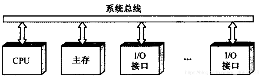
- Single Bus: Uses a single system bus to connect the CPU, memory, and I/O devices.
- Features: In a single bus structure, all logic components connected to the bus must operate at high speed to be able to quickly obtain bus control when needed and quickly release bus control when no longer needed.
- Otherwise, since one bus is shared by multiple functional components, it may cause significant time delays.
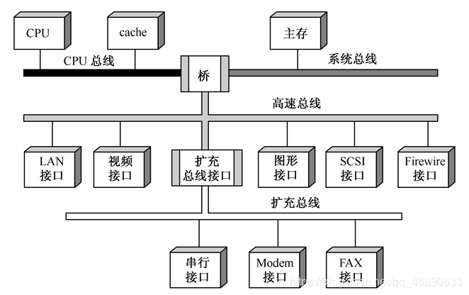
- Multiple Bus: Multiple buses are used for interconnection between CPU, main memory, and I/O. As shown in the figure.
- High-speed CPU bus: Used between CPU and cache - System bus: Main memory is connected to it. High-speed LAN (100Mb/s), video interface, graphics interface, SCSI interface (supporting local disk drives and other peripherals), and Firewire interface (supporting high-capacity I/O devices) can be connected to the high-speed bus. The high-speed bus is connected to the expansion bus through an expansion bus interface, where serial I/O devices can be connected. - CPU bus, system bus, and high-speed bus are interconnected through bridges. A bridge is essentially a logic circuit with buffering, conversion, and control functions. - Multiple bus structures allow high-speed, medium-speed, and low-speed devices to be connected to different buses working simultaneously, improving bus efficiency and throughput, and processor architecture changes do not affect the high-speed bus.
- High-speed CPU bus: Used between CPU and cache - System bus: Main memory is connected to it. High-speed LAN (100Mb/s), video interface, graphics interface, SCSI interface (supporting local disk drives and other peripherals), and Firewire interface (supporting high-capacity I/O devices) can be connected to the high-speed bus. The high-speed bus is connected to the expansion bus through an expansion bus interface, where serial I/O devices can be connected. - CPU bus, system bus, and high-speed bus are interconnected through bridges. A bridge is essentially a logic circuit with buffering, conversion, and control functions. - Multiple bus structures allow high-speed, medium-speed, and low-speed devices to be connected to different buses working simultaneously, improving bus efficiency and throughput, and processor architecture changes do not affect the high-speed bus.
喜欢的话,留下你的评论吧~